CHINESE
 ENGLISH


Dividing head structure and dividing method
Dividing head is one of the important accessories, milling machine commonly used to install the milling cant, dividing the work, and processing spiral groove, etc.
Dividing head effect:
1) with all sorts of dividing method (simple dividing, double entry points degrees, differential dividing) for all kinds of dividing the work.
2) the piece to the point of view of the need to install, so the cutting processing (such as milling cant, etc.).
3) milling spiral groove, will dividing head axle and milling machine longitudinal workbench hang with ball screw "exchange gear" after, when the connected mobile, dividing head of workpiece can obtain spiral movement.
1 universal dividing head structure
Figure 1 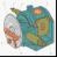 is the commonly used dividing head structure, and the main base, rotating body, indexing plate, spindle etc. With the rotation axis in the vertical plane within the body rotation. Usually in the main shaft front installation three claws chuck or a top, and use it to install the workpiece. Turn the handle can make the spindle drive the certain Angle, this is called turned indexing.
Figure 1 universal dividing head structure
1-dividing the handle 2, indexing plate 3-the top 4, 5-6 axis rotation body-7-fan base clip
Dividing head installation and adjustment:
1. Dividing head spindle axis and milling machine work tables floor parallel degree of correction as shown in figure 2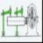 shows, with a diameter of 40 mm long 400 mm calibration great insert dividing head when the Lord within the workbench mesa as a benchmark, with BaiFenBiao measurement correction on both ends, when both ends great value consistent, the dividing head spindle axis and workbench mesa parallel.
Figure 2
2. Dividing head spindle and knife stem axis vertical degree of correction as shown in figure 3 shows, will correct in his great when of the table inside the head and correction of great touch in the lateral side (or), and then moving workbench contact longitudinal, when BaiFenBiao pointer stable indicates that dividing head spindle and tool rod vertical axis.
Figure 3
3. Dividing head and top ask shaft degree after correction calibrated dividing head first, and then will correct great clamping the degree after between head and top with top after correction and dividing head high, and finally the spindle correction the coaxial tolerance, that is, between two top the axis of the parallel to the workbench mesa and perpendicular to the milling cutters stem, as shown in figure 4.
Figure 4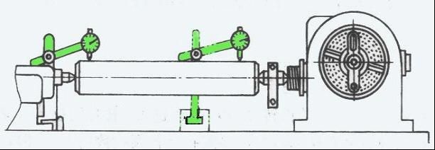
2 simple dividing method
According to the figure 5 shows the dividing head drive, it is known that the transmission line graph is: the handle and gear transmission ratio of 1:1)-(worm and worm gear transmission ratio (for)-one main axle. Can calculate the handle and the axis of transmission ratio is 1:1/40, namely the handle turn around, spindle is turned the 1/40 circle.
Figure 5 universal dividing head transmission schemes
1-2-1:1 spiral gear transmission axis 3-4-dial one worm gear
5-6-hang 1:1 gear transmission axle 7-indexing plate 8-pins
If want to make the work Z, every time the equal degrees (axis) to 1 / Z turn, turn the handle is dividing head that number for n turn round, they should meet the following proportions:
namely
Visible, as long as the dividing the handle turned 40 / Z turn, can make spindle around 1 / Z to turn. Example: now to milling gear Z = 17 gears. Every time dividing, dividing the handle RPM for:
Figure 6 
 indexing plate
That is to say, every minute a tooth, the handle to the whole circle turn more 2 turn 6/17 circle. The circle is 6/17 by indexing plate (figure 6) to control. Domestic dividing head with a general two pieces of indexing plate. Indexing plate on both sides have many different number of isometric hole circle.
The first piece of indexing plate each hole in the lap of the positive for: 24, 25, 28, 30, 34, 37; Opposite the hole is in the lap of the 38, 39, 41, 42, 43. The second piece of indexing plate each hole in the lap of the positive for: 46, 47, 49, 51, 53, 54; Opposite the hole is in the lap of the 57, 58, 59, 62, 66..
Dividing before, first in the above to find the common denominator 17 multiples of hole circle (for example: 34, 51) to choose a, if choose 34. The handle of the pins pull out, make the handle turned the whole circle, then 2 along the hole hole for 34 laps of the circle around 12 pitch. This is the main shaft, to turn around 1/17 indexing purposes.
In order to avoid every time points when the number of repeat hole bored and ensure the handle turned pitch accurate, the indexing plate of the two fan clip 1 and 2, the Angle between adjustment to just to handle turned the integer circle hole spacing. So every time dividing can be done quickly and accurately.
The above is to use indexing plate the whole circle hole spacing and should be turned pitch than, to deal with dividing the handle to turn a point form of the integer circle the rotation of the problem. This is simple dividing method. Production and Angle dividing method, the direct dividing method and differential dividing method, etc.
Formula: N (handle) = 40 RPM (dividing head destiny) / Z (the workpiece on the score) were: on the score 12 N = 40/12 = 3 4/12 = 3 8/24 that is dividing head turn the handle 3 laps, again in the hole on 24 circle turn eight pitch. Also can check list: (the table below only a partial)
Characteristic menu type dividing method dividing table
The workpiece on the score indexing plate number aperture count turn the handle of the pitch for the turn on the score indexing plate number aperture count turn the handle the pitch that turned number
2 any 20-11 66 3 42
3 and 8 and 13 24 8
4 any 10 to 13 and 3 3
5 any 8-14 28 2 24
6 June 24 16 15 24 2 16
7 and 5 20 16 24 2 12
8 any 5-17 34 2 12
9 54 4 24 18 54 2 12
10 any 4-19 and 2 of 4
In addition, points for attention when dividing head gap problem.
Latest News
Contact Us

Name: Nina
Tel: 0086-0769-81177281
Fax: 0086-0769-81177281
Mobile: 0086-13712515491
E-mail: [email protected]
Skype: toolsharpener
QQ: 19641516791
WeChat: 0086 13712515491
Whatsapp: 0086 17727718926
Add: No 1 industrial avenue, Hengli Town,Dongguan city,Guangdong provience,China


 Skype Chat
 WhatsApp
  Mail inquiry
 QQ online